Integrated Photonics Modules for Better Synthetic Aperture Radars
Project SPACEBEAM was an EU-funded HORIZON 2020 effort to develop an enhanced radar receiver for Earth observation applications. The integrated photonic module would enable continuous wideband signal beamforming and frequency-agnostic photonic down-conversion for the direct digitisation of output signals. Our projects leader, Ahmad Mohammad, coordinated project activities within LioniX International, and will present the results of the project in a multi-part series based on his article published in Journal of Lightwave Technology. Welcome to the world of spaceborne radars!
Earth observation technologies revolutionized climate change research and contributed to the pursuit of global sustainability goals over the past few decades. However, observing the Earth from space is highly dependent on weather conditions and time constraints, factors that often limit data acquisition. For solving these issues, a breakthrough solution was developed: the first-ever photonics-assisted receiver module for scan-on-receive synthetic aperture radar. This hybrid photonic integrated circuit (PIC) can execute precise and continuous beamforming-on-receive for wideband signals sourced from a 12-antenna elements array. Remarkably, it has the capacity to synthesize up to three simultaneous beams.
Why use photonic chips for Synthetic Aperture Radars?
Synthetic aperture radar (SAR) is a widely used spaceborne Earth observation technique. It provides radar-enabled elevation images which can be acquired independent of weather conditions and time of the day, unlike optical sensors.
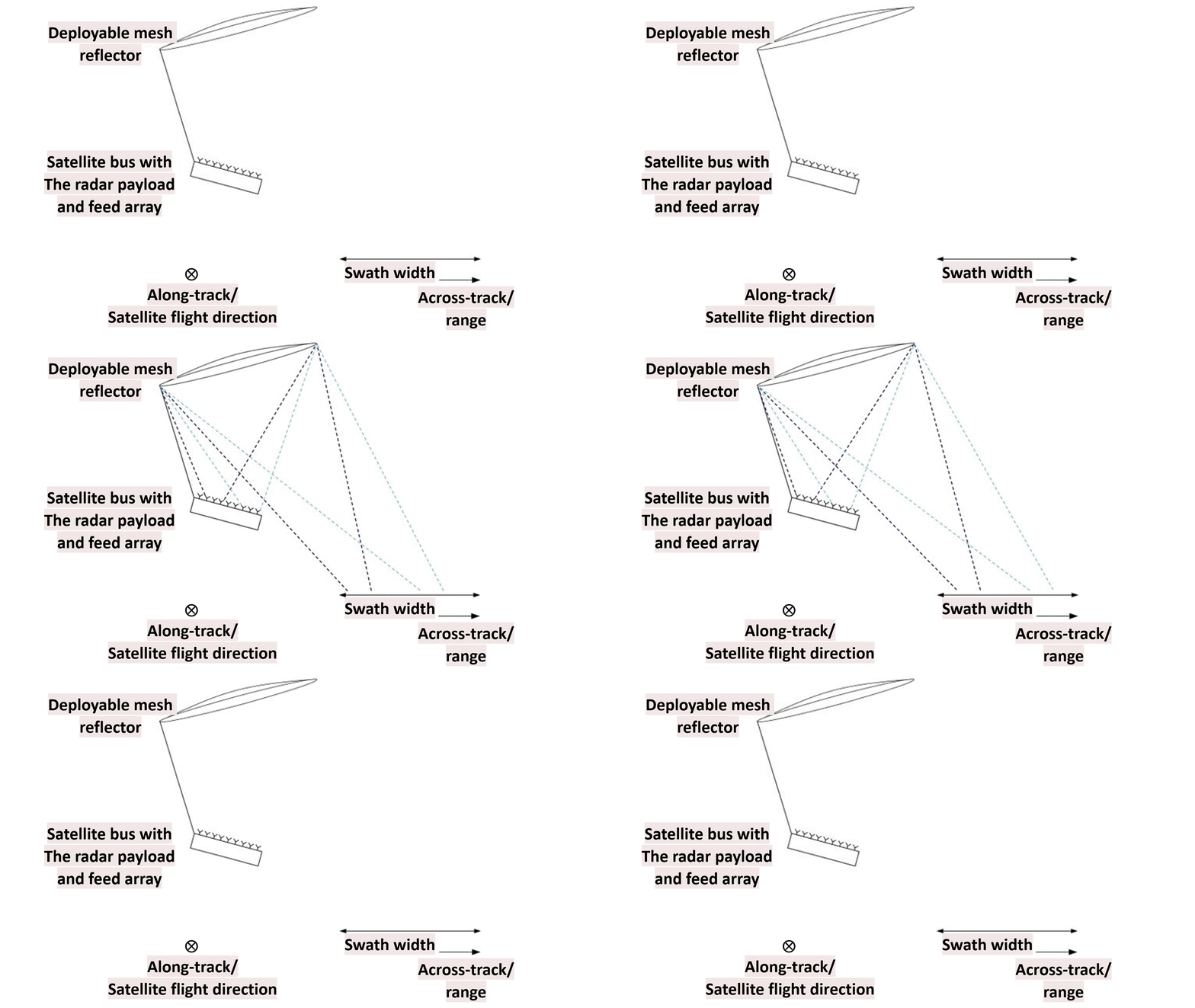
Future spaceborne SAR instruments require instantaneous imaging of wide areas at a high resolution, which can be realized by advanced SAR imaging methods, such as “scan-on-receive” (SCORE). The animation below illustrates the SCORE concept, where a wide swath is illuminated in the transmit mode, and multiple simultaneous receive beams are steered in the receive mode across the swath to receive the radar echoes stemming from different transmit events.
Figure 1: Illustration of the SCORE imaging mode
Project SPACEBEAM (SPACE SAR system with integrated photonic BEAMforming) aimed at achieving a swath 5 times wider than the current spaceborne SAR systems while guaranteeing 1.5 m spatial resolution on both along- and across-track directions.
The SPACEBEAM device would consume low power thanks to photonic integration and the use of the Lead Zirconate Titanate (PZT) actuators. The total power consumption per module was estimated at 3.5 W. SPACEBEAM also provides reconfigurable 12×3 beamforming and signal down-conversion functionalities by exploiting a reconfigurable Blass matrix.
Designing photonic modules for SCORE-SAR receivers
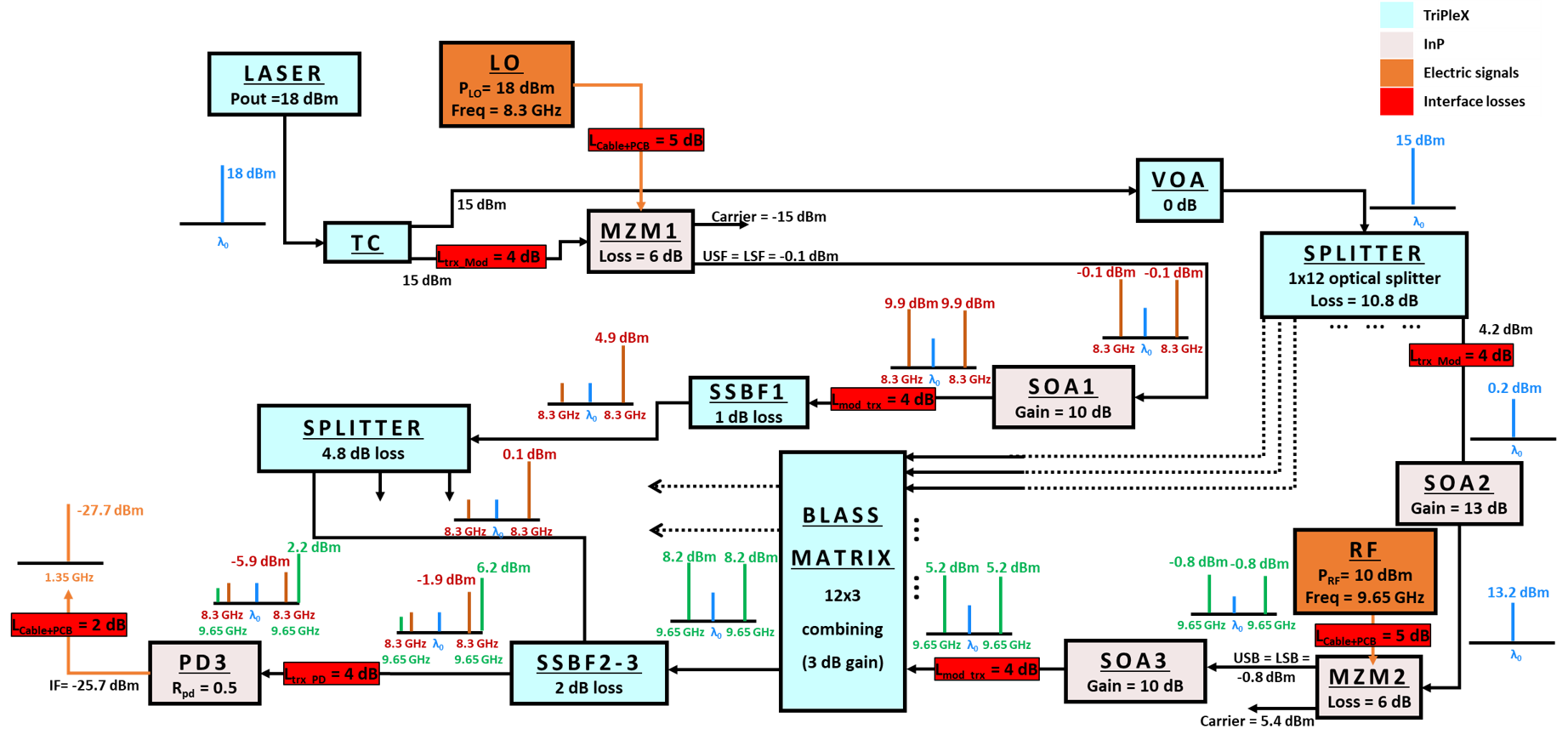
The goal of the project was to design a reconfigurable 12×3 beamformer for a SCORE-SAR receiver in the X-band at 9.65 GHz with minimum bandwidth of 450 MHz and a down-conversion capability to a low intermediate frequency (IF = 1.35 GHz). To achieve this, a functional design of the PIC was developed and simulated (Fig. 2), where a laser is split into two paths: one is modulated by a local oscillator (LO) and the other is split further by a 1×12 splitter and modulated by 12 RF signals in Mach–Zehnder modulators (MZMs). This approach creates optical side tones for the LO and RF which are combined, at the end, and heterodyned in photodiodes to achieve signal down-conversion. Each modulator is monolithically integrated with semiconductor optical amplifiers (SOAs) to boost the optical signal power. Filtering stages are added to combine signals and to reduce the amplified spontaneous emission (ASE) noise from the SOAs. A 12×3 Blass switching matrix is used to perform delay, phase, and amplitude control to the modulated signals and to combine them to form the receiving beams.
Figure 2: The functional design of the PIC.
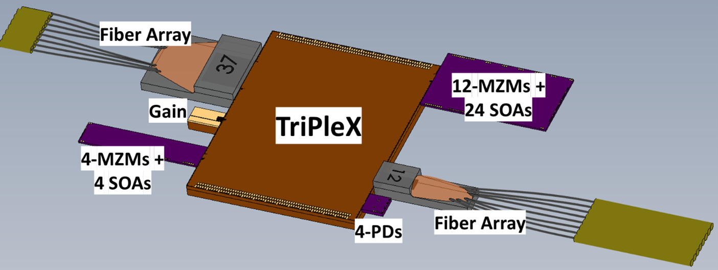
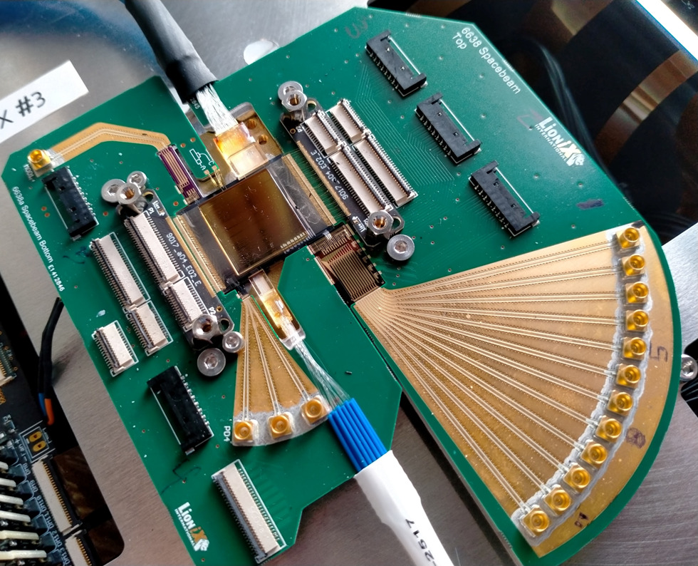
The proposed design combines active components on indium phosphide (InP) and passive components on TriPleX® silicon nitride (Si₃N₄). The two platforms are hybridly integrated, as illustrated in the 3D model in Fig. 3. In full, the LioniX-assembled module (Fig. 4) is a hybrid integration of the following chips:
- An InP gain chip which serves as a gain section of the laser.
- InP modulators chips with arrays of MZMs for electrical to optical (E-O) conversion of the LO and the RF signals. These modulators are monolithically integrated with SOAs to boost the optical signals powers.
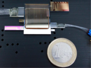
Figure 3 : A photo of a hybrid PIC.
- A TriPleX® Si₃N₄ chip with ultra low-loss waveguides. The chip acts as a laser cavity and simultaneously conducts signal filtering, signal splitting and combining, and optical beamforming.
- A InP photodiodes (PDs) chip with an array of photodiodes with a bandwidth of up to 40 GHz to realize optical to electrical (O-E) conversion
Figure 4: 3D model of the hybrid PIC.
Figure 5: A photo of the hybrid assembly and the PCB around it.
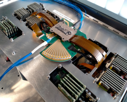
Figure 6: A photo of the module mounted on the control electronics box.
We put the rest of our vertically integrated capabilities to work, too: LioniX also designed the printed circuit boards (PCBs) around the hybrid assembly and wire-bonded them to the photonic chips (Fig. 5). LioniX also built a control electronics unit, which we called SaBox (Fig. 6), to control and tune the different sections in the module. We developed a software tool with a graphical user interface for this purpose.
Then we did it a few more times: LioniX built several of these systems: 6 hybrid modules and 4 SaBoxes. They were distributed among SPACEBEAM partners to perform functional tests, environmental tests, and space-compliant packaging. At LioniX, we demonstrated frequency down-conversion functionality, which is one of the subjects of a recent paper in JLT. Our partners demonstrated beamforming functionality and conducted environmental tests. Space-compliant packaging, replacing regular PCBs for a Low Temperature Co-fired Ceramics one, for the module was tested by Tyndall. Here, the regular PCB is replaced with a ceramic one, called LTCC (Low Temperature Co-fired Ceramics). On my next blog article, I will go over some of these results from our partners. In the meantime, feel free to reach out to me via email or LinkedIn if you would like to talk about our work for SPACEBEAM.

Dr. Ahmad Mohammad received the joint M.Sc. degree in photonic networks engineering from Aston University, Birmingham, U.K., and Scuola Superiore Sant’Anna, Italy, in 2015, within the European Erasmus Mundus Program. Then, he joined the Ultra-Fast Photonics Group at University College London (UCL), as a Marie-Curie Early-Stage Researcher within the H2020 FiWiN5G project, where he also received his Ph.D. degree in integrated photonics for millimeter wave transmitters and receivers in 2019. Since then, he has been working at LioniX, as a projects leader in the Microwave Photonics Systems department.

